General Purpose Input/Output (GPIO) pins are any pin on a integrated circuit that can be programmed to act as either an input or an output. These pins are commonly used in embedded systems and electronics for interfacing with external components or devices.
If GPIO pins are being used to transmit security relevant information, they could become a point of attack in a system. For instance, a distributed system could implement implement micro-controllers that communicate with a central computer system via GPIO’s.
To simulate this behavior, we will be getting a ESP32 micro-controller to communicate with as Raspberry Pi 4 using GPIO pins.
Connecting the Devices
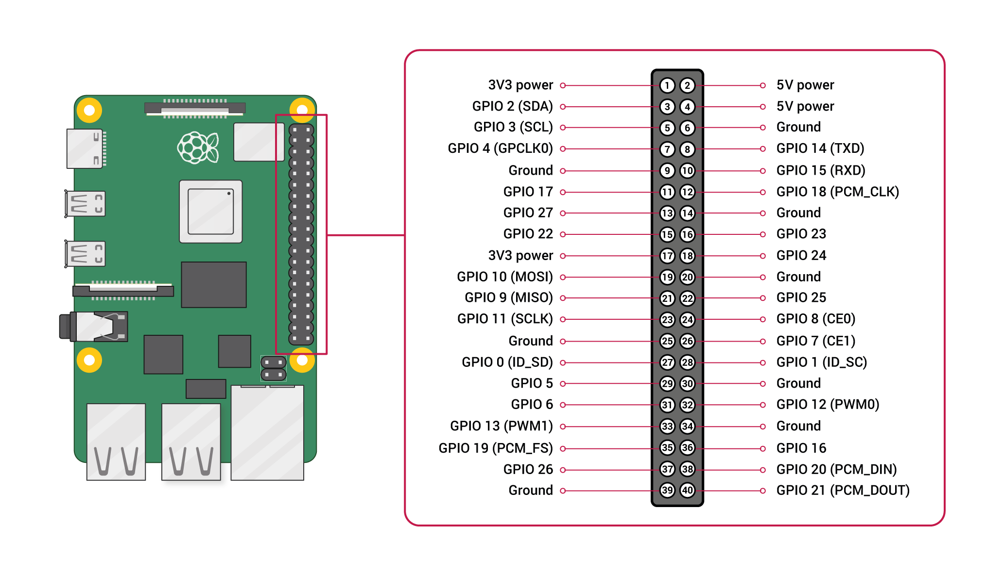
On the Raspberry Pi side, we will be using GPIO 4 (Pin 7), and GND (Pin 6). The below diagram illustrates which pin is which based on the official documentation.

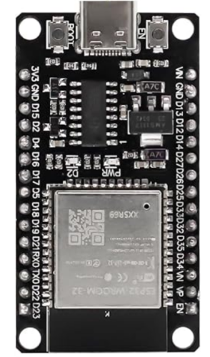
I’m using an ESP32-WROOM-32 device. It’s worth noting other ESP32 variants will likely have different pin outs, so it’s worth checking the documentation.
The ESP32 typically has labelled ports. Connect GND to GND on the Raspberry Pi. Connect D4 (GPIO4) on the ESP32 to GPIO 4 (Pin 7) on the Raspberry Pi.

Be aware that some of the GPIO pins on the raspberry Pi are 5v. The ESP32 can handle a maximum of 3.3v, so don’t randomly choose pins to be used or this may result in damage.
Configuring the ESP32
We can use the Arduino IDE to program the device. Download the IDE from here. Open the IDE, and go to Preferences > Additional Board Manager URL’s and enter the following url:
https://espressif.github.io/arduino-esp32/package_esp32_index.json
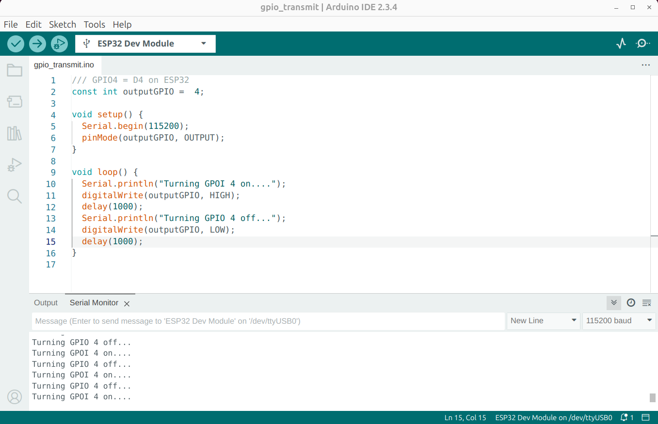
After doing this you should be able to select ESP32 Dev Module as a device. Enter the following code as a new sketch.
1 2 3 4 5 6 7 8 9 10 11 12 13 14 15 16 | /// GPIO4 = D4 on ESP32const int outputGPIO = 4; void setup() { Serial.begin(115200); pinMode(outputGPIO, OUTPUT);}void loop() { Serial.println("Turning GPOI 4 on...."); digitalWrite(outputGPIO, HIGH); delay(1000); Serial.println("Turning GPIO 4 off..."); digitalWrite(outputGPIO, LOW); delay(1000);} |
The code is just changing the GPIO state between 0v and 3.3v. GPIO’s are configured either as inputs or outputs. In this example, the ESP32 will be the transmitter (output).
Upload the code to the device, and select Tools > Serial monitor. You should see the device changing the GPIO state.

Configuring the Raspberry Pi
I’m running Kali Linux on the Raspberry Pi, so we will need to install some packages to get this working.
1 | sudo apt install python3-rpi.gpio rpi.gpio-common |
With that installed, we should be able to read the GPIO values using Python:
1 2 3 4 5 6 7 8 9 10 11 12 13 14 15 16 17 18 19 20 21 22 23 24 25 | #!/usr/bin/python3import RPi.GPIO as GPIOimport timeinputGPIO = 7GPIO.setmode(GPIO.BOARD)GPIO.setup(inputGPIO, GPIO.IN)# Initialize previous state to a value that is different from the initial state.previous_state = GPIO.input(inputGPIO)while True: time.sleep(0.1) # Read the current state of the GPIO pin current_state = GPIO.input(inputGPIO) # Check if the state has changed if current_state != previous_state: print('GPIO status changed to =', current_state) previous_state = current_state # Update the previous state to the current stateGPIO.cleanup() |
Running the script, we can see the GPIO state is changing each second.
1 2 3 4 5 6 7 8 9 | sudo python3 gpio2.py14:10:04 GPIO status changed to = 014:10:05 GPIO status changed to = 114:10:06 GPIO status changed to = 014:10:07 GPIO status changed to = 114:10:08 GPIO status changed to = 014:10:09 GPIO status changed to = 114:10:10 GPIO status changed to = 014:10:11 GPIO status changed to = 1 |
In Conclusion
Interfacing with GPIO’s is fairly trivial in Linux. Although this is a very simple technology, it can be overlooked during security assessments. If an adversary has physical access to GPIO pins, at the very least they should be able to determine what information is being transmitted using a logic analyser.