Universal Asynchronous Receiver-Transmitter (UART), is a hardware communication protocol used for serial communication. It enables devices to exchange data asynchronously, meaning that they don’t need to share a clock signal. Instead, they use start bits, stop bits, and a specified baud rate to synchronize data transmission.
Electronics devices such as routers often leave UART ports active. By interfacing with the port, we may be able to gain command line access to the device.
The following pins are normally used for a UART connection.
VCC: This is the positive supply voltage. It provides power to the circuit.
GND: This is the ground connection, which serves as the reference point for the voltage levels in the circuit.
RX (Receive): This pin is used to receive data. In serial communication, it’s where incoming signals are received.
TX (Transmit): This pin is used to send data. In serial communication, it’s where outgoing signals are transmitted.
Verifying UART Pins
Looking at the router below, we can see the UART pins have been labelled.
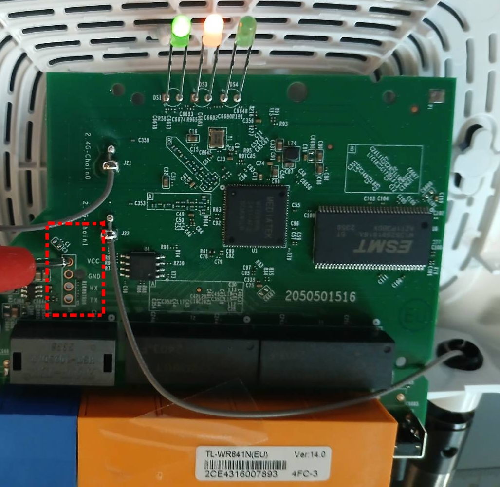
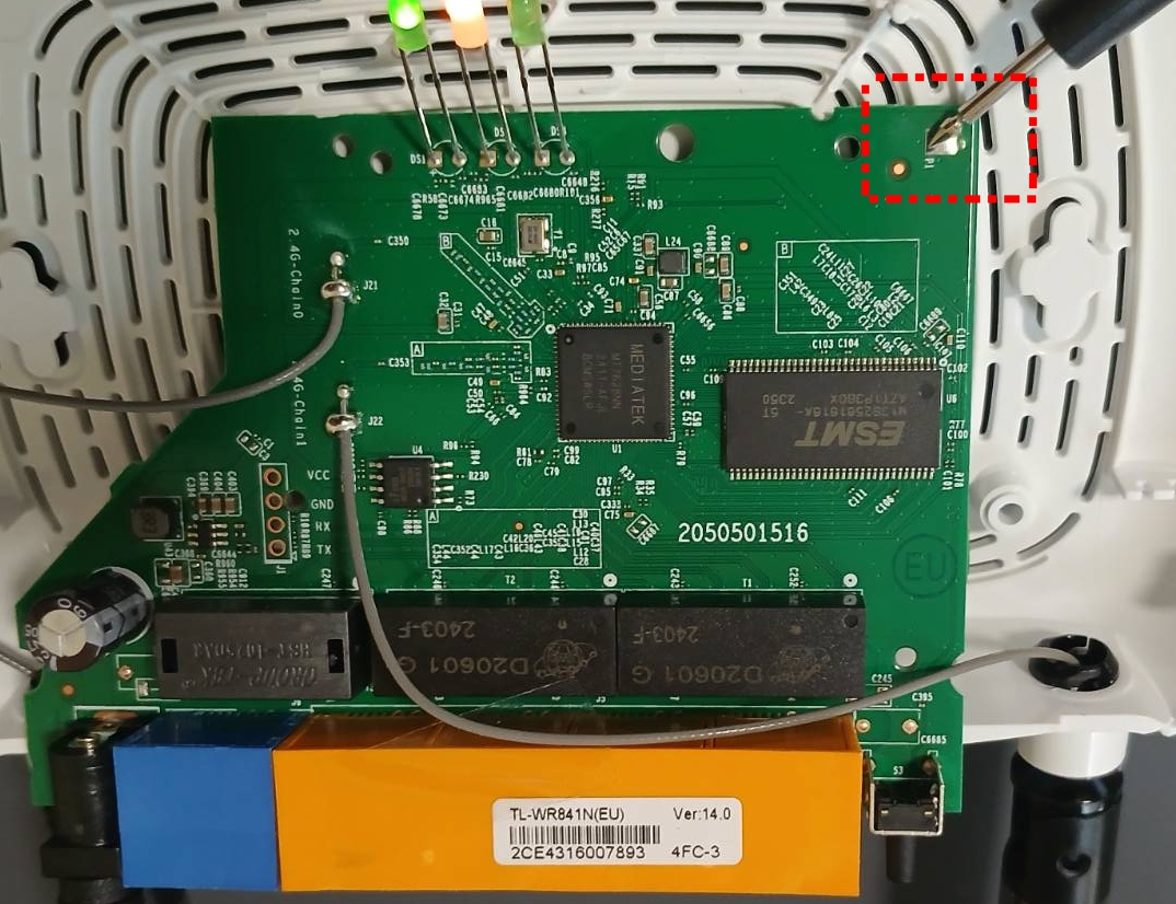
Although the UART pin has a ground, there is an additional ground labelled P1 on the board. This can be determined by performing a continuity test.
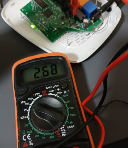
With our negative probe on the UART ground, and our positive probe on the VCC, we should see a reading of 3.3v on our multi-meter. Doing the same to the TX pin should also read 3.3v. If we measure the TX voltage as the device reboots, you should see the voltage drop and go back to 3.3v as data is being transmitted. This is a good indication that the port is active.
Connecting a Logic Analyzer
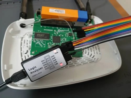
A UART logic analyser will allow us to see the data being sent on the port. Connect channel CH1 of the logic analyser to the TX port and the CND port to the GND on the board.
PulseView
PulseView is an open-source software tool used for visualizing and analyzing data from hardware interfaces like logic analyzers and oscilloscopes. It’s part of the Sigrok project, which aims to provide cross-platform, open-source tools for handling different types of test and measurement equipment. Pulseview is available in the Kali Linux package repository.
Open PulseView, select your device, and set the sample size to 100M / 1 Mhz.
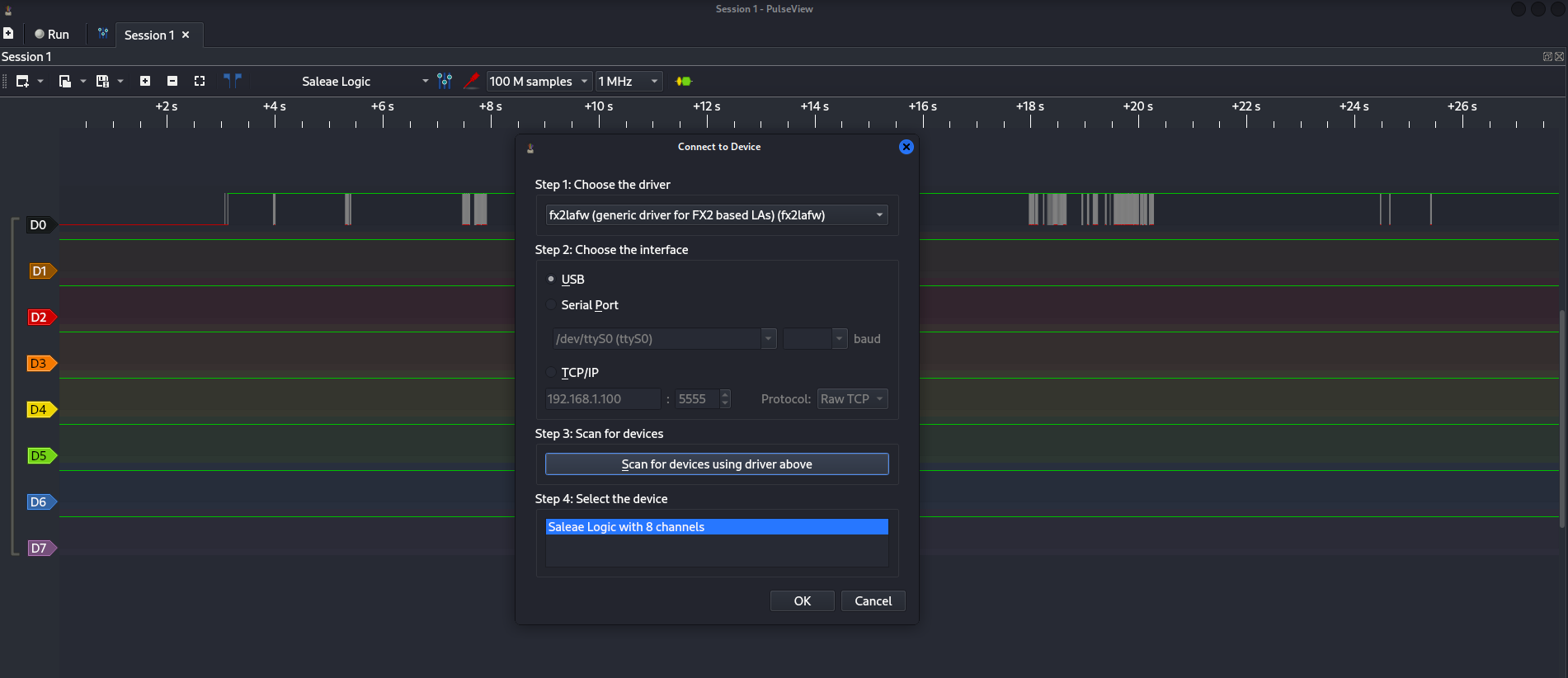
Start a capture, then power up the target device. Save the output when it’s complete.
Decoding the Messages
Click to add a decoder (using the green and yellow symbol in the top bar), and select UART. Change the data format to ASCII, then zoom into the graph and you should see the decoded text. You may need to alter the baud rate, although the default of 115200 should work.

Zooming in further will show the bits being transmitted based on the voltage modulation.

Getting a shell
We can use a USB to TTL serial adapter to connect to the device and get a shell. I would recommend you avoid using a USB extension lead, as this seems to cause issues.
Connect the GND on the adapter to the GND on the device. The RX and TX should be connected, but swapped (i.e RX > TX, TX > RX).
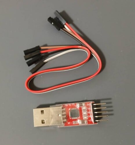

With that in place, we can connect to the device using Putty or GNU screen and extract the systems password database.
1 2 3 4 5 6 7 8 9 10 11 12 13 14 15 16 17 18 19 20 21 22 23 24 25 26 27 28 29 30 31 32 33 34 35 36 37 38 39 40 41 42 43 44 45 46 47 48 49 50 51 52 53 54 55 56 57 58 59 60 61 62 63 64 65 66 67 68 69 70 71 72 73 74 75 76 77 78 79 80 81 82 83 84 85 86 87 88 89 90 91 92 93 94 | U-Boot 1.1.3 (Aug 16 2022 - 11:38:19)Board: Ralink APSoC DRAM: 32 MBrelocate_code Pointer at: 81fc0000flash manufacture id: 1c, device id 70 16Warning: un-recognized chip ID, please update bootloader!============================================Ralink UBoot Version: 4.3.0.0--------------------------------------------ASIC 7628_MP (Port5<->None)DRAM component: 256 Mbits DDR, width 16DRAM bus: 16 bitTotal memory: 32 MBytesFlash component: SPI FlashDate:Aug 16 2022 Time:11:38:19============================================icache: sets:512, ways:4, linesz:32 ,total:65536dcache: sets:256, ways:4, linesz:32 ,total:32768 ##### The CPU freq = 580 MHZ #### estimate memory size =32 MbytesRESET MT7628 PHY!!!!!!continue to starting system. 0disable switch phyport...3: System Boot system code via Flash.(0xbc010000)do_bootm:argc=2, addr=0xbc010000## Booting image at bc010000 ... Uncompressing Kernel Image ... OKNo initrd## Transferring control to Linux (at address 8000c150) ...## Giving linux memsize in MB, 32Starting kernel ...LINUX started... THIS IS ASICLinux version 2.6.36 (jenkins@sohoici) (gcc version 4.6.3 (Buildroot 2012.11.1) ) #1 Tue Aug 16 11:41:42 CST 2022 The CPU feqenuce set to 575 MHz MIPS CPU sleep mode enabled.CPU revision is: 00019655 (MIPS 24Kc)Software DMA cache coherencyDetermined physical RAM map: memory: 02000000 @ 00000000 (usable)Initrd not found or empty - disabling initrdZone PFN ranges: Normal 0x00000000 -> 0x00002000Movable zone start PFN for each nodeearly_node_map[1] active PFN ranges 0: 0x00000000 -> 0x00002000Built 1 zonelists in Zone order, mobility grouping on. Total pages: 8128Kernel command line: console=ttyS1,115200 root=/dev/mtdblock2 rootfstype=squashfs init=/sbin/initPID hash table entries: 128 (order: -3, 512 bytes)Dentry cache hash table entries: 4096 (order: 2, 16384 bytes)Inode-cache hash table entries: 2048 (order: 1, 8192 bytes)Primary instruction cache 64kB, VIPT, , 4-waylinesize 32 bytes.Primary data cache 32kB, 4-way, PIPT, no aliases, linesize 32 bytesWriting ErrCtl register=0007fa53Readback ErrCtl register=0007fa53Memory: 29228k/32768k available (2180k kernel code, 3540k reserved, 583k data, 156k init, 0k highmem)NR_IRQS:128console [ttyS1] enabledCalibrating delay loop... 386.04 BogoMIPS (lpj=772096)pid_max: default: 4096 minimum: 301Mount-cache hash table entries: 512NET: Registered protocol family 16bio: create slab <bio-0> at 0~ # ls -ladrwxrwxr-x 8 194 webdrwxr-xr-x 10 0 vardrwxrwxr-x 4 38 usrdrwxr-xr-x 13 0 sysdrwxrwxr-x 2 236 sbindr-xr-xr-x 66 0 procdrwxrwxr-x 2 3 mntlrwxrwxrwx 1 11 linuxrc -> bin/busyboxdrwxrwxr-x 3 665 libdrwxrwxr-x 5 359 etcdrwxrwxr-x 5 1274 devdrwxrwxr-x 2 280 bindrwxrwxr-x 13 177 ..drwxrwxr-x 13 177 .~ # [ util_execSystem ] 185: prepareDropbear cmd is "dropbearkey -t rsa -f /var/tmp/dropbear/dropbear_rsa_host_key"~ # cat /etc/passwdadmin:$1$$iC.dUsGpxNNJGeOm1dFio/:0:0:root:/:/bin/shdropbear:x:500:500:dropbear:/var/dropbear:/bin/shnobody:*:0:0:nobody:/:/bin/sh |
In Conclusion
With a foothold on the target system, you should then be able to copy binaries across to maintain access over a network connection.